US5507280A - Anesthesia rebreathing system - Google Patents
Anesthesia rebreathing system Download PDFInfo
- Publication number
- US5507280A US5507280A US08/405,582 US40558295A US5507280A US 5507280 A US5507280 A US 5507280A US 40558295 A US40558295 A US 40558295A US 5507280 A US5507280 A US 5507280A
- Authority
- US
- United States
- Prior art keywords
- patient
- gas
- valve
- port
- overflow
- Prior art date
- Legal status (The legal status is an assumption and is not a legal conclusion. Google has not performed a legal analysis and makes no representation as to the accuracy of the status listed.)
- Expired - Fee Related
Links
Images


Classifications
-
- A—HUMAN NECESSITIES
- A61—MEDICAL OR VETERINARY SCIENCE; HYGIENE
- A61M—DEVICES FOR INTRODUCING MEDIA INTO, OR ONTO, THE BODY; DEVICES FOR TRANSDUCING BODY MEDIA OR FOR TAKING MEDIA FROM THE BODY; DEVICES FOR PRODUCING OR ENDING SLEEP OR STUPOR
- A61M16/00—Devices for influencing the respiratory system of patients by gas treatment, e.g. mouth-to-mouth respiration; Tracheal tubes
- A61M16/01—Devices for influencing the respiratory system of patients by gas treatment, e.g. mouth-to-mouth respiration; Tracheal tubes specially adapted for anaesthetising
-
- A—HUMAN NECESSITIES
- A61—MEDICAL OR VETERINARY SCIENCE; HYGIENE
- A61M—DEVICES FOR INTRODUCING MEDIA INTO, OR ONTO, THE BODY; DEVICES FOR TRANSDUCING BODY MEDIA OR FOR TAKING MEDIA FROM THE BODY; DEVICES FOR PRODUCING OR ENDING SLEEP OR STUPOR
- A61M16/00—Devices for influencing the respiratory system of patients by gas treatment, e.g. mouth-to-mouth respiration; Tracheal tubes
- A61M16/0057—Pumps therefor
- A61M16/0081—Bag or bellow in a bottle
-
- A—HUMAN NECESSITIES
- A61—MEDICAL OR VETERINARY SCIENCE; HYGIENE
- A61M—DEVICES FOR INTRODUCING MEDIA INTO, OR ONTO, THE BODY; DEVICES FOR TRANSDUCING BODY MEDIA OR FOR TAKING MEDIA FROM THE BODY; DEVICES FOR PRODUCING OR ENDING SLEEP OR STUPOR
- A61M16/00—Devices for influencing the respiratory system of patients by gas treatment, e.g. mouth-to-mouth respiration; Tracheal tubes
- A61M16/08—Bellows; Connecting tubes ; Water traps; Patient circuits
- A61M16/0816—Joints or connectors
- A61M16/0833—T- or Y-type connectors, e.g. Y-piece
-
- A—HUMAN NECESSITIES
- A61—MEDICAL OR VETERINARY SCIENCE; HYGIENE
- A61M—DEVICES FOR INTRODUCING MEDIA INTO, OR ONTO, THE BODY; DEVICES FOR TRANSDUCING BODY MEDIA OR FOR TAKING MEDIA FROM THE BODY; DEVICES FOR PRODUCING OR ENDING SLEEP OR STUPOR
- A61M16/00—Devices for influencing the respiratory system of patients by gas treatment, e.g. mouth-to-mouth respiration; Tracheal tubes
- A61M16/08—Bellows; Connecting tubes ; Water traps; Patient circuits
- A61M16/0816—Joints or connectors
- A61M16/0841—Joints or connectors for sampling
- A61M16/085—Gas sampling
-
- A—HUMAN NECESSITIES
- A61—MEDICAL OR VETERINARY SCIENCE; HYGIENE
- A61M—DEVICES FOR INTRODUCING MEDIA INTO, OR ONTO, THE BODY; DEVICES FOR TRANSDUCING BODY MEDIA OR FOR TAKING MEDIA FROM THE BODY; DEVICES FOR PRODUCING OR ENDING SLEEP OR STUPOR
- A61M16/00—Devices for influencing the respiratory system of patients by gas treatment, e.g. mouth-to-mouth respiration; Tracheal tubes
- A61M16/10—Preparation of respiratory gases or vapours
- A61M16/1005—Preparation of respiratory gases or vapours with O2 features or with parameter measurement
- A61M16/1015—Preparation of respiratory gases or vapours with O2 features or with parameter measurement using a gas flush valve, e.g. oxygen flush valve
-
- A—HUMAN NECESSITIES
- A61—MEDICAL OR VETERINARY SCIENCE; HYGIENE
- A61M—DEVICES FOR INTRODUCING MEDIA INTO, OR ONTO, THE BODY; DEVICES FOR TRANSDUCING BODY MEDIA OR FOR TAKING MEDIA FROM THE BODY; DEVICES FOR PRODUCING OR ENDING SLEEP OR STUPOR
- A61M16/00—Devices for influencing the respiratory system of patients by gas treatment, e.g. mouth-to-mouth respiration; Tracheal tubes
- A61M16/20—Valves specially adapted to medical respiratory devices
-
- A—HUMAN NECESSITIES
- A61—MEDICAL OR VETERINARY SCIENCE; HYGIENE
- A61M—DEVICES FOR INTRODUCING MEDIA INTO, OR ONTO, THE BODY; DEVICES FOR TRANSDUCING BODY MEDIA OR FOR TAKING MEDIA FROM THE BODY; DEVICES FOR PRODUCING OR ENDING SLEEP OR STUPOR
- A61M16/00—Devices for influencing the respiratory system of patients by gas treatment, e.g. mouth-to-mouth respiration; Tracheal tubes
- A61M16/0045—Means for re-breathing exhaled gases, e.g. for hyperventilation treatment
-
- A—HUMAN NECESSITIES
- A61—MEDICAL OR VETERINARY SCIENCE; HYGIENE
- A61M—DEVICES FOR INTRODUCING MEDIA INTO, OR ONTO, THE BODY; DEVICES FOR TRANSDUCING BODY MEDIA OR FOR TAKING MEDIA FROM THE BODY; DEVICES FOR PRODUCING OR ENDING SLEEP OR STUPOR
- A61M16/00—Devices for influencing the respiratory system of patients by gas treatment, e.g. mouth-to-mouth respiration; Tracheal tubes
- A61M16/0057—Pumps therefor
- A61M16/0078—Breathing bags
-
- A—HUMAN NECESSITIES
- A61—MEDICAL OR VETERINARY SCIENCE; HYGIENE
- A61M—DEVICES FOR INTRODUCING MEDIA INTO, OR ONTO, THE BODY; DEVICES FOR TRANSDUCING BODY MEDIA OR FOR TAKING MEDIA FROM THE BODY; DEVICES FOR PRODUCING OR ENDING SLEEP OR STUPOR
- A61M16/00—Devices for influencing the respiratory system of patients by gas treatment, e.g. mouth-to-mouth respiration; Tracheal tubes
- A61M16/20—Valves specially adapted to medical respiratory devices
- A61M16/208—Non-controlled one-way valves, e.g. exhalation, check, pop-off non-rebreathing valves
Definitions
- This invention relates generally to systems for administering anesthesia gas to medical patients.
- U.S. Pat. Nos. 3,814,091 and 3,901,230 disclose anesthesia rebreathing systems characterized by a geometry which preferentially vents expired alveolar gas, rich in carbon dioxide (CO 2 ), while retaining fresh gas and initially expired dead space gas, rich in oxygen (O 2 ), for rebreathing by the patient to thus minimize the need for CO 2 absorption.
- the systems include a patient circuit incorporating an overflow tube whose entrance is located very close to the patient.
- the overflow tube exits at a patient overflow (commonly referred to as "Pop-Off") valve which is located close to an anesthesia machine where it can be conveniently controlled by an attending anesthetist.
- Pop-Off patient overflow
- the overflow tube entrance By locating the overflow tube entrance close to the patient, it functions to preferentially vent alveolar gas through the patient overflow (i.e., Pop-Off) valve and save dead space and unbreathed gas within the tubing and reservoir of the patient circuit.
- the Pop-Off valve is operable in two different modes, i.e., (1) as a manually controlled variable orifice for spontaneous, manually assisted or controlled ventilation and (2) as an automatically controlled valve responding to a positive control pressure for manually assisted or controlled ventilation or mechanically controlled ventilation.
- the enhanced system described in U.S. Pat. No. 3,901,230 can be viewed as functionally including (1) a patient circuit and (2) a ventilator/isolator (V/I) circuit for controlling gas volume and pressure in the patient circuit.
- the described structural embodiment can be viewed as physically including (1) a single use portion and (2) a reusable portion. The embodiment is configured so that the single use portion forms most of the patient circuit with the reusable portion forming the V/I circuit and part of the patient circuit, e.g. the patient Pop-Off Valve.
- the V/I circuit includes a constant volume (e.g., rigid) container (forming part of the system's reusable portion) within which a variable volume patient breathing reservoir (e.g., a flaccid bag) (forming part of the single use portion) is accommodated.
- a constant volume patient breathing reservoir e.g., a flaccid bag
- the pressure within the rigid container is controlled (1) during manually assisted or controlled ventilation, by an attending anesthetist squeezing an outside bag and (2) during mechanically controlled ventilation by a conventional ventilator.
- the pressure variations in the rigid container are applied to the patient circuit via the flexible walls of the patient bag. Cross contamination is eliminated because the patient expired gas cannot come into contact with the reusable portion components exposed to inspired gas.
- U.S. Pat. No. 4,991,576 discloses an anesthesia rebreathing system which retains the advantages of the systems disclosed in U.S. Pat. Nos. 3,814,091 and 3,901,230 and which incorporates additional features to enhance ease of use and safe operation. It describes first and second embodiments which differ from one another in that the first embodiment uses overflow gas from the patient circuit as working gas for the V/I circuit whereas the second embodiment derives V/I working gas from a high pressure gas source (preferably dry medical grade oxygen).
- a high pressure gas source preferably dry medical grade oxygen
- the improvements include a control subsystem for maintaining the patient overflow (i.e., Pop-Off) valve closed during each breathing cycle until the patient breathing reservoir is full.
- the patient reservoir comprises a flaccid bag and the control subsystem includes a "full bag” sensor which, via a pneumatic cylinder, physically holds the patient Pop-Off valve closed except when the bag is full.
- the full-bag sensor preferably comprises a lever mounted adjacent to the patient breathing bag and biased to a first position. As the volume of the bag increases, its wall engages the lever to move it from its first position to a second or full-bag position. The lever, in turn, releases the aforementioned pneumatic cylinder to allow the Pop-Off valve to open.
- the present invention is directed to an improved anesthesia rebreathing system configured for preventing gas overflow from a patient Pop-Off valve until the patient breathing reservoir is full, resulting in enhanced ease of use, safety, and efficient utilization of anesthesia gas.
- overflow from a patient Pop-Off valve is inhibited by an Overflow Blocker valve mounted downstream in series opposition to the patient Pop-Off valve.
- the Overflow Blocker valve is, however, forced open when the patient breathing reservoir, typically a flaccid bag, is full. Thus, until the patient bag is full, the loss of patient exhaled dead space gas and fresh gas is prevented.
- the patient Pop-Off valve in preferred embodiments of the invention comprises a unidirectional valve configured to permit gas flow only in a first direction from its entrance port to its exit port, i.e., out of the patient circuit.
- the series opposing Overflow Blocker valve is configured so that it normally closes in response to gas flow in said first direction.
- a mechanical member responding to the volume of the patient bag filling to a predetermined volume physically opens the Overflow Blocker valve to allow patient overflow gas to flow therepast.
- the patient overflow gas is used as the working gas for a ventilator/isolator (V/I) circuit.
- V/I ventilator/isolator
- the Overflow Blocker valve is located between the patient Pop-Off valve and the working gas entrance to a fixed volume container accommodating the patient bag. Gas can flow into the container from the patient Pop-Off valve only when the patient bag is full and the Overflow Blocker valve is thus open. Excess gas from the container is vented through an adjustable V/I circuit Pop-Off valve to a scavenging system.
- V/I circuit working gas is derived from a high pressure gas source (preferably dry medical grade oxygen) rather than from the patient Pop-Off valve.
- a high pressure gas source preferably dry medical grade oxygen
- This second embodiment is similar to the first embodiment to the extent that patient overflow gas flow past the patient Pop-Off valve occurs only when the Overflow Blocker valve is open as a consequence of the patient bag being full.
- this second embodiment differs from the first embodiment in that gas flow past the Overflow Blocker valve flows to a scavenging system rather than into the patient bag container.
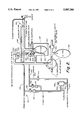
- FIG. 1 is a functional block diagram of a first operational embodiment in accordance with the invention
- FIG. 2 is a functional block diagram of a second operational embodiment in accordance with the invention.
- FIG. 3 depicts an implementation of a preferred Overflow Blocker Valve useful in the embodiment of FIG. 1;
- FIG. 4A depicts an implementation of a preferred Overflow Blocker Valve useful in the embodiment of FIG. 2;
- FIG. 4B is a sectional view taken substantially along the plane 4B--4B of FIG. 4A.
- FIG. 1 is a block diagram of a first preferred embodiment in accordance with the present invention.
- the dashed line 80 is intended to generally represent a physical interface between a detachable single use structural portion 82 and a permanent reusable structural portion 84.
- the detachable portion 82 includes most of the components forming a functional patient circuit 86.
- a patient Pop-Off valve 88 may be properly viewed as functionally being part of the patient circuit 86 although it is physically included in the system's permanent portion 84.
- the permanent portion 84 primarily comprises a ventilator/isolator (V/I) circuit or subsystem 90 for controlling the gas volume and pressure in the patient circuit 86.
- V/I ventilator/isolator
- the patient circuit portion 86 is comprised of a device for communicating with a patient's airway, e.g., an elbow fitting 100 adapted to be coupled to a patient mask or endotracheal tube.
- the fitting 100 communicates with a breathing tube 102 which is shown as including a single limb for both expiratory and inspiratory gas movement but which can comprise separate inspiratory and expiratory tubes.
- the distal end of the breathing tube 102 is connected to the elbow fitting 100.
- the proximal end of the breathing tube 102 defines a fresh gas interface port 103 which is connected across the interface 80 to a fresh gas interface port 105 on the permanent portion 84.
- a variable volume patient breathing reservoir e.g., flaccid bag 104 communicates with breathing tube 102 close to the interface port 103.
- the permanent portion fresh gas interface port 105 is coupled to a fresh gas supply line 106.
- the patient circuit portion 82 additionally includes an overflow tube 108 having a tube entrance located close to the patient, i.e. fitting 100.
- the proximal end of the overflow tube 108 at interface port 107 is connected to an interface port 109 across the interface 80.
- Interface port 109 opens to entrance port 110 of the Pop-Off valve 88.
- the Pop-Off valve 88 preferably comprises a check valve element 111 slightly biased closed against a valve seat 112.
- the check valve element 111 is configured to permit gas flow therepast in a first direction only, i.e., into entrance port 110 and out from exit port 113 to Overflow Blocker valve 114.
- Overflow Blocker valve 114 includes check valve element 115 and valve seat 116 and is configured in series opposition to Pop-Off valve 88 so that it normally closes in response to gas flow out of Pop-Off valve exit port 113. Accordingly, the series opposed Pop-Off and Overflow Blocker valves normally prevent any outflow from overflow tube 108 past Pop-Off valve 88.
- Overflow Blocker valve check valve element 115 is configured to be physically opened by lever 117 acting on lifter stem 118 when patient bag 104 is full. Lifter stem 118 is mounted in guide 119 for reciprocal vertical movement.
- Overflow Blocker valve 114 is located between Pop-Off valve exit port 113 and the entrance port 120 to a constant volume, e.g., rigid, container 122 in which the patient bag 104 is removably accommodated.
- the lever 117 comprised of short section 123 and long section 124, is mounted in container 122 for pivoting around pivot pin 125.
- lever 117 will pivot clockwise to the dashed line position 126. In this position, the Overflow Blocker valve element 115 is seated on valve seat 116 and outflow through Pop-Off valve exit port 113 is prevented.
- Changes in pressure within the container 122 are transferred to the patient circuit 86 via the flexible walls of the patient bag 104. Increases or decreases in gas volume within the patient bag are reflected by gas movement out of or into the rigid container 122 via control port 127 coupled via tube 128 to a mode selector valve 130.
- Mode selector valve 130 can be selectively rotated by a user to either the full line position or the dashed line position depicted in FIG. 1.
- valve 130 couples control port 127 to outside bag 132 and to a user adjustable V/I circuit Pop-Off valve 134.
- valve 130 couples control port 127 to a mechanical ventilator (not shown).
- the selector valve 130 will be placed in the solid line position for manually assisted and controlled ventilation or spontaneous ventilation.
- spontaneous ventilation fresh gas will continually be supplied via supply line 106 to the patient bag 104 and breathing tube 102.
- the patient circuit Pop-Off valve 88 closed.
- the patient bag 104 decreases in size as gas flows to the patient.
- the outside bag 132 also decreases in size as gas flows therefrom to the patient bag container 122. Under these conditions, the Overflow Blocker valve 114 is closed.
- gas flows from the patient and the fresh gas supply to the patient bag 104.
- gas is displaced from the container 122 to the outside bag 132.
- the adjustable V/I circuit Pop-Off valve 134 will vent excess gas to a scavenging system via port 136.
- the patient bag 104 becomes sufficiently full to pivot lever 117 to its full line position and thus open the Overflow Blocker valve 114. Consequently, gas from the patient flows through the overflow tube 108 and past the patient circuit Pop-Off valve 88 and Overflow Blocker valve 114 into the container 122. Excess gas is vented through valve 134.
- the Overflow Blocker valve 114 When the Overflow Blocker valve 114 is open, the gas expired by the patient flows almost directly into the overflow tube 108. Simultaneously, the fresh gas inflow via supply line 106 pushes previously exhaled gas in the breathing tube 102, into the overflow tube 108. Consequently, the alveolar gas, that is last gas out of the patient, is the gas first into the overflow tube 108 for priority venting. At the conclusion of exhalation, both the patient bag 104 and the outside bag 132 are full and the inhalation sequence begins again.
- the system operates similarly during manually assisted and controlled ventilation except that typically the V/I circuit Pop-Off valve 134 is incrementally adjusted by the attending anesthetist so that a proper volume of gas is vented to scavenging.
- the anesthetist squeezes the outside bag 132 sending gas with a positive pressure to the container 122 where it presses on the patient bag 104 which in turn sends gas to the patient via the breathing tube 102.
- the pressure in the container 122 opens the Overflow Blocker valve 114 and closes the patient circuit Pop-Off valve 88.
- gas flows into the patient from the patient bag 104 and the fresh gas supply 106 during inspiration. Expiration and the end expiratory phase during manually assisted and controlled ventilation are essentially the same as during spontaneous ventilation.
- control port 127 is coupled to a mechanical ventilator (not shown).
- the mechanical ventilator acts essentially the same as the outside bag 132 being squeezed by the attending anesthetist.
- FIG. 2 comprises a block diagram of a second preferred embodiment in accordance with the present invention.
- the detachable portion 82' of FIG. 2 can be identical to that shown in FIG. 1 and similarly communicates across interface 80' with a permanent portion 84'.
- the permanent portion 84' differs from the permanent portion 84 of FIG. 1 primarily as a consequence of using supplemental gas, e.g., dry medical grade oxygen, supplied via inlet tube 200, as V/I circuit working gas to fill, via tube 202, rigid container 122' (via port 204) and outside bag 132' (via port 206).
- supplemental gas e.g., dry medical grade oxygen
- V/I circuit working gas does not present a cross contamination risk inasmuch as gas from the overflow tube 108 can only flow away from the patient past the Patient Pop-Off valve 88 and there is no path for the V/I circuit working gas to reenter the patient circuit.
- patient expired gas for V/I circuit working gas is that it is generally of high humidity and may have impurities, such as blood or phlegm which could, over extended periods, affect the reliability of valving and flow in the V/I circuit as well as the mechanical ventilator.
- this risk is minimal if the permanent portion is properly maintained, the system of FIG. 2 avoids this possibility by using a high pressure gas supply to provide working gas.
- FIG. 2 differs from that of FIG. 1 in that instead of using a check valve as the Patient Pop-Off Valve 88, FIG. 2 uses a balanced valve 220 for this purpose.
- Valve 220 includes a diaphragm or valve element 222 which is normally slightly biased closed, i.e., in contact against valve seat 224. A sufficient positive pressure from overflow tube 108' can overcome this bias pressure to open valve 220 to permit gas flow from tube 108' past valve seat 224 and through tube 228 to port 230 of Overflow Blocker valve 234. As seen in FIGS.
- valve 234 is comprised of valve housing 236 which, in addition to port 230, defines port 238 which leads to a scavenging system (not shown).
- a valve element 244 is mounted in housing 236 on lifter stem 246 for reciprocal movement toward and away from valve seat 250.
- Valve 234 is opened by the action of lever 260 acting on lifter stem 246 when patient bag 104' is full.
- lever 260 is comprised of short and long sections 262, 264 and is mounted in container 122' for pivotal movement. More particularly, short section 262 has a rod 265 secured thereto extending through bearings 266. Rod 265 has a short arm 267 secured thereto in housing 236 for engaging lifter stem 246. In its normal state, the lever 260 will hang in a position which permits lifter stem 246 to drop so as to enable valve element 244 to seal against valve seat 250. As bag 104' fills beyond a predetermined volume, its wall engages lever 260 to pivot it clockwise (as viewed in FIG. 2) to lift lifter stem 246 (via rod 265 and arm 267) and open valve 234, enabling gas to flow from tube 108' past Patient Pop-Off valve 220 and via Overflow Blocker valve port 238 to scavenging.
- FIG. 2 further differs from FIG. 1 in that a flush valve 300 is provided.
- the valve 300 includes an inlet port 302 and outlet port 304.
- An attending anesthetist can operate flush button 306 to flush gas from supply 200 to clear both the patient and V/I circuits.
Abstract
A system for administering anesthesia gas and for preventing gas overflow until the patient breathing reservoir is full in order to enhance ease of use, safety, and efficient utilization of anesthesia gas. Overflow from a patient Pop-Off valve is inhibited by an Overflow Blocker valve mounted downstream in series opposition to the patient Pop-Off valve. The Overflow Blocker valve is forced open when the patient bag is full. Thus, until the patient bag is full, the loss of patient exhaled dead space gas and fresh gas is prevented.
Description
This is a continuation-in-part of U.S. patent application Ser. No. 07/960,935, filed Oct. 14, 1992, now U.S. Pat. No. 5,398,675, which is incorporated herein by reference.
This invention relates generally to systems for administering anesthesia gas to medical patients.
U.S. Pat. Nos. 3,814,091 and 3,901,230 disclose anesthesia rebreathing systems characterized by a geometry which preferentially vents expired alveolar gas, rich in carbon dioxide (CO2), while retaining fresh gas and initially expired dead space gas, rich in oxygen (O2), for rebreathing by the patient to thus minimize the need for CO2 absorption. The systems include a patient circuit incorporating an overflow tube whose entrance is located very close to the patient. The overflow tube exits at a patient overflow (commonly referred to as "Pop-Off") valve which is located close to an anesthesia machine where it can be conveniently controlled by an attending anesthetist. By locating the overflow tube entrance close to the patient, it functions to preferentially vent alveolar gas through the patient overflow (i.e., Pop-Off) valve and save dead space and unbreathed gas within the tubing and reservoir of the patient circuit. The Pop-Off valve is operable in two different modes, i.e., (1) as a manually controlled variable orifice for spontaneous, manually assisted or controlled ventilation and (2) as an automatically controlled valve responding to a positive control pressure for manually assisted or controlled ventilation or mechanically controlled ventilation.
The enhanced system described in U.S. Pat. No. 3,901,230 can be viewed as functionally including (1) a patient circuit and (2) a ventilator/isolator (V/I) circuit for controlling gas volume and pressure in the patient circuit. The described structural embodiment can be viewed as physically including (1) a single use portion and (2) a reusable portion. The embodiment is configured so that the single use portion forms most of the patient circuit with the reusable portion forming the V/I circuit and part of the patient circuit, e.g. the patient Pop-Off Valve. The V/I circuit includes a constant volume (e.g., rigid) container (forming part of the system's reusable portion) within which a variable volume patient breathing reservoir (e.g., a flaccid bag) (forming part of the single use portion) is accommodated. The pressure within the rigid container is controlled (1) during manually assisted or controlled ventilation, by an attending anesthetist squeezing an outside bag and (2) during mechanically controlled ventilation by a conventional ventilator. The pressure variations in the rigid container are applied to the patient circuit via the flexible walls of the patient bag. Cross contamination is eliminated because the patient expired gas cannot come into contact with the reusable portion components exposed to inspired gas.
U.S. Pat. No. 4,991,576 discloses an anesthesia rebreathing system which retains the advantages of the systems disclosed in U.S. Pat. Nos. 3,814,091 and 3,901,230 and which incorporates additional features to enhance ease of use and safe operation. It describes first and second embodiments which differ from one another in that the first embodiment uses overflow gas from the patient circuit as working gas for the V/I circuit whereas the second embodiment derives V/I working gas from a high pressure gas source (preferably dry medical grade oxygen).
Applicants' parent application discloses improvements particularly suited for use in systems of the type described in U.S. Pat. No. 4,991,576, for enhancing ease of use, safe operation, and efficient use of anesthesia gas. More particularly, the improvements include a control subsystem for maintaining the patient overflow (i.e., Pop-Off) valve closed during each breathing cycle until the patient breathing reservoir is full. As a consequence, loss of patient exhaled dead space gas and fresh gas is minimized. In the preferred embodiment described, the patient reservoir comprises a flaccid bag and the control subsystem includes a "full bag" sensor which, via a pneumatic cylinder, physically holds the patient Pop-Off valve closed except when the bag is full. The full-bag sensor preferably comprises a lever mounted adjacent to the patient breathing bag and biased to a first position. As the volume of the bag increases, its wall engages the lever to move it from its first position to a second or full-bag position. The lever, in turn, releases the aforementioned pneumatic cylinder to allow the Pop-Off valve to open.
The present invention is directed to an improved anesthesia rebreathing system configured for preventing gas overflow from a patient Pop-Off valve until the patient breathing reservoir is full, resulting in enhanced ease of use, safety, and efficient utilization of anesthesia gas.
In accordance with the invention, overflow from a patient Pop-Off valve is inhibited by an Overflow Blocker valve mounted downstream in series opposition to the patient Pop-Off valve. The Overflow Blocker valve is, however, forced open when the patient breathing reservoir, typically a flaccid bag, is full. Thus, until the patient bag is full, the loss of patient exhaled dead space gas and fresh gas is prevented.
The patient Pop-Off valve in preferred embodiments of the invention comprises a unidirectional valve configured to permit gas flow only in a first direction from its entrance port to its exit port, i.e., out of the patient circuit. The series opposing Overflow Blocker valve is configured so that it normally closes in response to gas flow in said first direction. However, a mechanical member responding to the volume of the patient bag filling to a predetermined volume physically opens the Overflow Blocker valve to allow patient overflow gas to flow therepast.
In a first preferred embodiment, the patient overflow gas is used as the working gas for a ventilator/isolator (V/I) circuit. In this embodiment, the Overflow Blocker valve is located between the patient Pop-Off valve and the working gas entrance to a fixed volume container accommodating the patient bag. Gas can flow into the container from the patient Pop-Off valve only when the patient bag is full and the Overflow Blocker valve is thus open. Excess gas from the container is vented through an adjustable V/I circuit Pop-Off valve to a scavenging system.
In a second preferred embodiment, V/I circuit working gas is derived from a high pressure gas source (preferably dry medical grade oxygen) rather than from the patient Pop-Off valve. This second embodiment is similar to the first embodiment to the extent that patient overflow gas flow past the patient Pop-Off valve occurs only when the Overflow Blocker valve is open as a consequence of the patient bag being full. However, this second embodiment differs from the first embodiment in that gas flow past the Overflow Blocker valve flows to a scavenging system rather than into the patient bag container.
FIG. 1 is a functional block diagram of a first operational embodiment in accordance with the invention;
FIG. 2 is a functional block diagram of a second operational embodiment in accordance with the invention;
FIG. 3 depicts an implementation of a preferred Overflow Blocker Valve useful in the embodiment of FIG. 1;
FIG. 4A depicts an implementation of a preferred Overflow Blocker Valve useful in the embodiment of FIG. 2; and
FIG. 4B is a sectional view taken substantially along the plane 4B--4B of FIG. 4A.
Inasmuch as preferred embodiments of the present invention are similar in many respects to the embodiments disclosed in Applicants' prior U.S. Pat. No. 5,398,675 the description herein will focus primarily on the features which distinguish the present invention. Although these features will be described with reference to systems of the type described in said U.S. Pat. No. 5,398,675 it is pointed out they are also applicable to many other anesthesia gas delivery systems.
Attention is now directed to FIG. 1 which is a block diagram of a first preferred embodiment in accordance with the present invention. As in applicants parent application, the dashed line 80 is intended to generally represent a physical interface between a detachable single use structural portion 82 and a permanent reusable structural portion 84. The detachable portion 82 includes most of the components forming a functional patient circuit 86. However, a patient Pop-Off valve 88 may be properly viewed as functionally being part of the patient circuit 86 although it is physically included in the system's permanent portion 84. The permanent portion 84 primarily comprises a ventilator/isolator (V/I) circuit or subsystem 90 for controlling the gas volume and pressure in the patient circuit 86.
The patient circuit portion 86 is comprised of a device for communicating with a patient's airway, e.g., an elbow fitting 100 adapted to be coupled to a patient mask or endotracheal tube. The fitting 100 communicates with a breathing tube 102 which is shown as including a single limb for both expiratory and inspiratory gas movement but which can comprise separate inspiratory and expiratory tubes. The distal end of the breathing tube 102 is connected to the elbow fitting 100. The proximal end of the breathing tube 102 defines a fresh gas interface port 103 which is connected across the interface 80 to a fresh gas interface port 105 on the permanent portion 84. A variable volume patient breathing reservoir, e.g., flaccid bag 104 communicates with breathing tube 102 close to the interface port 103. The permanent portion fresh gas interface port 105 is coupled to a fresh gas supply line 106. The patient circuit portion 82 additionally includes an overflow tube 108 having a tube entrance located close to the patient, i.e. fitting 100. The proximal end of the overflow tube 108 at interface port 107 is connected to an interface port 109 across the interface 80. Interface port 109 opens to entrance port 110 of the Pop-Off valve 88.
The Pop-Off valve 88 preferably comprises a check valve element 111 slightly biased closed against a valve seat 112. The check valve element 111 is configured to permit gas flow therepast in a first direction only, i.e., into entrance port 110 and out from exit port 113 to Overflow Blocker valve 114.
As shown in FIGS. 1 and 3 Overflow Blocker valve 114 includes check valve element 115 and valve seat 116 and is configured in series opposition to Pop-Off valve 88 so that it normally closes in response to gas flow out of Pop-Off valve exit port 113. Accordingly, the series opposed Pop-Off and Overflow Blocker valves normally prevent any outflow from overflow tube 108 past Pop-Off valve 88. However, Overflow Blocker valve check valve element 115 is configured to be physically opened by lever 117 acting on lifter stem 118 when patient bag 104 is full. Lifter stem 118 is mounted in guide 119 for reciprocal vertical movement.
Note in FIG. 1 that Overflow Blocker valve 114 is located between Pop-Off valve exit port 113 and the entrance port 120 to a constant volume, e.g., rigid, container 122 in which the patient bag 104 is removably accommodated. The lever 117, comprised of short section 123 and long section 124, is mounted in container 122 for pivoting around pivot pin 125. When the volume of patient bag 104 is less than a predetermined threshold, lever 117 will pivot clockwise to the dashed line position 126. In this position, the Overflow Blocker valve element 115 is seated on valve seat 116 and outflow through Pop-Off valve exit port 113 is prevented.
On the other hand, when patient bag 104 fills beyond a predetermined threshold volume, the bag wall contacts lever long section 124 to pivot lever 117 clockwise to the full line position depicted in FIG. 1. This causes the lever short section 123 to lift lifter stem 118 and unseat valve element 115 to thus permit gas to flow out of exit port 113 and into container 122 via entrance port 120.
Changes in pressure within the container 122 are transferred to the patient circuit 86 via the flexible walls of the patient bag 104. Increases or decreases in gas volume within the patient bag are reflected by gas movement out of or into the rigid container 122 via control port 127 coupled via tube 128 to a mode selector valve 130.
In the operation of the system of FIG. 1, the selector valve 130 will be placed in the solid line position for manually assisted and controlled ventilation or spontaneous ventilation. In spontaneous ventilation, fresh gas will continually be supplied via supply line 106 to the patient bag 104 and breathing tube 102. As the patient starts to inhale, he generates a negative pressure which holds the patient circuit Pop-Off valve 88 closed. The patient bag 104 decreases in size as gas flows to the patient. The outside bag 132 also decreases in size as gas flows therefrom to the patient bag container 122. Under these conditions, the Overflow Blocker valve 114 is closed. At the start of expiration, gas flows from the patient and the fresh gas supply to the patient bag 104. As the patient bag fills, gas is displaced from the container 122 to the outside bag 132. When the outside bag 132 is full, the adjustable V/I circuit Pop-Off valve 134 will vent excess gas to a scavenging system via port 136.
At some point during expiration, including the end expiratory phase, the patient bag 104 becomes sufficiently full to pivot lever 117 to its full line position and thus open the Overflow Blocker valve 114. Consequently, gas from the patient flows through the overflow tube 108 and past the patient circuit Pop-Off valve 88 and Overflow Blocker valve 114 into the container 122. Excess gas is vented through valve 134.
When the Overflow Blocker valve 114 is open, the gas expired by the patient flows almost directly into the overflow tube 108. Simultaneously, the fresh gas inflow via supply line 106 pushes previously exhaled gas in the breathing tube 102, into the overflow tube 108. Consequently, the alveolar gas, that is last gas out of the patient, is the gas first into the overflow tube 108 for priority venting. At the conclusion of exhalation, both the patient bag 104 and the outside bag 132 are full and the inhalation sequence begins again.
The system operates similarly during manually assisted and controlled ventilation except that typically the V/I circuit Pop-Off valve 134 is incrementally adjusted by the attending anesthetist so that a proper volume of gas is vented to scavenging. During inspiration, the anesthetist squeezes the outside bag 132 sending gas with a positive pressure to the container 122 where it presses on the patient bag 104 which in turn sends gas to the patient via the breathing tube 102. Additionally, the pressure in the container 122 opens the Overflow Blocker valve 114 and closes the patient circuit Pop-Off valve 88. Just as during spontaneous ventilation, gas flows into the patient from the patient bag 104 and the fresh gas supply 106 during inspiration. Expiration and the end expiratory phase during manually assisted and controlled ventilation are essentially the same as during spontaneous ventilation.
When the selector valve 130 is in the dashed line position, control port 127 is coupled to a mechanical ventilator (not shown). In this mode, the mechanical ventilator acts essentially the same as the outside bag 132 being squeezed by the attending anesthetist.
Attention is now directed to FIG. 2 which comprises a block diagram of a second preferred embodiment in accordance with the present invention. The detachable portion 82' of FIG. 2 can be identical to that shown in FIG. 1 and similarly communicates across interface 80' with a permanent portion 84'. The permanent portion 84' differs from the permanent portion 84 of FIG. 1 primarily as a consequence of using supplemental gas, e.g., dry medical grade oxygen, supplied via inlet tube 200, as V/I circuit working gas to fill, via tube 202, rigid container 122' (via port 204) and outside bag 132' (via port 206). The use of patient circuit gas as V/I circuit working gas in FIG. 1 does not present a cross contamination risk inasmuch as gas from the overflow tube 108 can only flow away from the patient past the Patient Pop-Off valve 88 and there is no path for the V/I circuit working gas to reenter the patient circuit. However, the disadvantage of using patient expired gas for V/I circuit working gas is that it is generally of high humidity and may have impurities, such as blood or phlegm which could, over extended periods, affect the reliability of valving and flow in the V/I circuit as well as the mechanical ventilator. Although this risk is minimal if the permanent portion is properly maintained, the system of FIG. 2 avoids this possibility by using a high pressure gas supply to provide working gas.
Thus, it will be noted that the system of FIG. 2 differs from that of FIG. 1 in that instead of using a check valve as the Patient Pop-Off Valve 88, FIG. 2 uses a balanced valve 220 for this purpose. Valve 220 includes a diaphragm or valve element 222 which is normally slightly biased closed, i.e., in contact against valve seat 224. A sufficient positive pressure from overflow tube 108' can overcome this bias pressure to open valve 220 to permit gas flow from tube 108' past valve seat 224 and through tube 228 to port 230 of Overflow Blocker valve 234. As seen in FIGS. 4A and 4B, valve 234 is comprised of valve housing 236 which, in addition to port 230, defines port 238 which leads to a scavenging system (not shown). A valve element 244 is mounted in housing 236 on lifter stem 246 for reciprocal movement toward and away from valve seat 250. When valve 234 is closed, i.e., with valve element 244 engaging valve seat 250, gas flow out of the overflow tube 108' is prevented because the Pop-Off valve 220 and Overflow Blocker valve 234 are in series opposition.
FIG. 2 further differs from FIG. 1 in that a flush valve 300 is provided. The valve 300 includes an inlet port 302 and outlet port 304. An attending anesthetist can operate flush button 306 to flush gas from supply 200 to clear both the patient and V/I circuits.
Operation of the system of FIG. 2 is similar to that described for FIG. 1 except it should be noted that when the flush button 306 is pressed, with the Selector Valve 130' in the outside bag position, not only will high pressure gas be supplied to the fresh gas line 106' via check valve 310, for flushing the patient circuit, but in addition high pressure gas will be supplied via check valve 312 to the V/I circuit including rigid container 122' and outside bag 132' to properly fill both circuits. Needle valves 316, 318 are preferably incorporated in the system of FIG. 2, as shown, for optimizing the flows to the patient and V/I circuits. Additionally, an adjustable needle valve 320 is provided to enable the user to adjust the flow of V/I working gas.
From the foregoing, it should now be appreciated that improvements in anesthesia gas delivery systems have been disclosed herein primarily for enhancing safe operation and increasing the efficiency of anesthesia gas usage. Although preferred implementations have been described, it should be understood that various alternatives can be readily used without departing from the spirit of the invention or the intended scope of the appended claims. For example only, although both described embodiments show the Overflow Blocker valve downstream from the Patient Pop-Off valve, this order could be reversed if desired.
Claims (12)
1. An anesthesia gas rebreathing system including:
a patient airway communication device;
a breathing tube having a first port coupled to said patient airway communication device and a second port configured for coupling to a fresh gas supply;
a variable volume patient reservoir having an entrance opening coupled to said breathing tube proximate to said breathing tube second port;
a patient overflow valve having an entrance port coupled to said breathing tube proximate to said first port and configured to permit gas flow from said entrance port to an exit port thereof in response to a positive pressure thereacross;
an overflow blocker valve having a first port and a second port, and configured to close in response to a positive pressure from said first port to said second port for preventing gas flow therethrough;
said patient overflow valve exit port coupled to said overflow blocker valve first port; and
sensor means responsive to said patient reservoir filling to a predetermined volume for holding said overflow blocker valve open to permit gas flow from said first to said second port thereof.
2. The system of claim 1 further including:
a constant volume container;
means in communication with said container for varying the pressure therein; and
means mounting said variable volume patient reservoir in said container whereby pressure variations therein will produce corresponding variations in said reservoir.
3. The system of claim 2 wherein said container defines a pressure control port; and
means coupled to said pressure control port for producing pressure variations in said container.
4. The system of claim 3 wherein said container defines a working gas entrance port and said overflow blocker valve second port is coupled to said container working gas entrance port.
5. The system of claim 3 wherein said overflow blocker valve second port is coupled to a scavenging system.
6. The system of claim 3 including a gas supply source coupled to said container entrance port for supplying working gas thereto.
7. The system of claim 3 wherein said means for producing pressure variations includes a gas container whose gas storage volume can be selectively varied by an operator.
8. The system of claim 1 wherein said patient reservoir includes an outer wall; and wherein
said sensor means is responsive to the location of said reservoir outer wall.
9. The system of claim 8 wherein said sensor means includes a mechanical member mounted for movement from a first to a second position in response to said patient reservoir filling to a predetermined volume; and
means coupling said mechanical member to said overflow blocker valve for holding said overflow blocker valve open when mechanical member is in said second position.
10. In a system for administering anesthesia gas to a patient including a breathing tube for supplying fresh gas to a patient's airway and a variable volume reservoir for alternately (1) storing gas from the patient during exhalation and (2) supplying stored gas to the patient during inhalation, means for controlling gas venting from said breathing tube, said means comprising:
a first valve coupled to said breathing tube for permitting gas flow therethrough in a first direction out of said breathing tube;
a second valve coupled in series with said first valve configured to normally prevent gas flow therethrough in said first direction; and
sensor means responsive to said reservoir filling to a predetermined volume for holding said second valve open to permit gas flow therethrough in said first direction.
11. The system of claim 10 wherein said reservoir includes an outer wall; an wherein
said sensor means is responsive to the location of said reservoir outer wall.
12. The system of claim 11 wherein said sensor means includes a mechanical member mounted for movement from a first to a second position in response to said patient reservoir filling to a predetermined volume; and
means coupling said mechanical member to said overflow blocker valve for holding said overflow blocker valve open when mechanical member is in said second position.
Priority Applications (1)
| Application Number | Priority Date | Filing Date | Title |
|---|---|---|---|
| US08/405,582 US5507280A (en) | 1992-10-14 | 1995-03-17 | Anesthesia rebreathing system |
Applications Claiming Priority (2)
| Application Number | Priority Date | Filing Date | Title |
|---|---|---|---|
| US07/960,935 US5398675A (en) | 1992-10-14 | 1992-10-14 | Anesthesia rebreathing system |
| US08/405,582 US5507280A (en) | 1992-10-14 | 1995-03-17 | Anesthesia rebreathing system |
Related Parent Applications (1)
| Application Number | Title | Priority Date | Filing Date |
|---|---|---|---|
| US07/960,935 Continuation-In-Part US5398675A (en) | 1992-10-14 | 1992-10-14 | Anesthesia rebreathing system |
Publications (1)
| Publication Number | Publication Date |
|---|---|
| US5507280A true US5507280A (en) | 1996-04-16 |
Family
ID=25503840
Family Applications (2)
| Application Number | Title | Priority Date | Filing Date |
|---|---|---|---|
| US07/960,935 Expired - Fee Related US5398675A (en) | 1992-10-14 | 1992-10-14 | Anesthesia rebreathing system |
| US08/405,582 Expired - Fee Related US5507280A (en) | 1992-10-14 | 1995-03-17 | Anesthesia rebreathing system |
Family Applications Before (1)
| Application Number | Title | Priority Date | Filing Date |
|---|---|---|---|
| US07/960,935 Expired - Fee Related US5398675A (en) | 1992-10-14 | 1992-10-14 | Anesthesia rebreathing system |
Country Status (3)
| Country | Link |
|---|---|
| US (2) | US5398675A (en) |
| AU (1) | AU5584994A (en) |
| WO (1) | WO1994008650A1 (en) |
Cited By (27)
| Publication number | Priority date | Publication date | Assignee | Title |
|---|---|---|---|---|
| WO1996040334A1 (en) * | 1995-06-07 | 1996-12-19 | Wayne State University | Delivery of oxygen-supersaturated physiologic solutions |
| WO1997000092A1 (en) * | 1995-06-14 | 1997-01-03 | Apotheus Laboratories, Ltd. | Scavanging method and apparatus for post anesthesia care |
| US5803064A (en) * | 1997-08-12 | 1998-09-08 | University Technology Corporation | Anesthesia system for use with magnetic resonance imaging systems |
| US6298848B1 (en) * | 1998-10-27 | 2001-10-09 | Siemens-Elema Ab | Device for flushing a deadspace in mechanical ventilation |
| US6354292B1 (en) * | 1997-03-19 | 2002-03-12 | Joseph A. Fisher | Elimination of vapour anaesthetics from patients after surgical procedures |
| US6467479B1 (en) * | 1998-10-09 | 2002-10-22 | The Brigham And Women's Hospital, Inc. | Method and apparatus for delivering a measured of a gas |
| US6612308B2 (en) * | 2000-03-31 | 2003-09-02 | Joseph Fisher | Portable isocapnia circuit and isocapnia method |
| US6634355B2 (en) * | 1999-06-11 | 2003-10-21 | Colas Marie-Jose | Single breath induction anesthesia apparatus |
| US6701915B1 (en) * | 1999-11-20 | 2004-03-09 | Michael Hermanussen | Device for inhaling medicaments using supported pressure respiration |
| US6745771B2 (en) * | 2001-01-10 | 2004-06-08 | Siemens Elema Ab | Anesthetic filter arrangement with variable retention of gas by the filter |
| US20040144385A1 (en) * | 2003-01-27 | 2004-07-29 | Leif Bromster | Manual ventilation system including manual bag filling valve |
| EP1449559A1 (en) * | 2003-02-18 | 2004-08-25 | INO Therapeutics GmbH | Metered delivery of therapeutic gas |
| US6799570B2 (en) | 2001-05-04 | 2004-10-05 | Joseph Fisher | Method of maintaining constant arterial PCO2 and measurement of anatomic and alveolar dead space |
| US6834647B2 (en) | 2001-08-07 | 2004-12-28 | Datex-Ohmeda, Inc. | Remote control and tactile feedback system for medical apparatus |
| US20050133033A1 (en) * | 2003-12-20 | 2005-06-23 | Drager Medical Ag & Co. | Device and process for metering breathing gas |
| US20060213517A1 (en) * | 2005-03-22 | 2006-09-28 | Mashak James N | Arrangement and method for controlling operational characteristics of medical equipment |
| US20060260612A1 (en) * | 2005-05-20 | 2006-11-23 | Drager Safety Ag & Co. Kgaa | Compressed air respirator |
| US20090205653A1 (en) * | 2005-04-29 | 2009-08-20 | Pawel Wisniewski | Breathing System |
| US20110065637A1 (en) * | 2009-09-11 | 2011-03-17 | David William Smith | Method to reduce SLOSH energy absorption and its damaging effects through the reduction of inelastic collisions in an organism |
| US20130211441A1 (en) * | 2010-10-22 | 2013-08-15 | Abigo Medical Ab | Device for Equalization of the Pressure in the Middle Ear |
| US8900169B2 (en) | 2013-03-15 | 2014-12-02 | Tbi Innovations, Llc | Methods and devices to reduce the likelihood of injury from concussive or blast forces |
| US9168045B2 (en) | 2009-09-11 | 2015-10-27 | Tbi Innovations, Llc | Device to reduce SLOSH energy absorption and its damaging effects through the reduction of the flow of one or more outflow vessels of the cranium |
| US9173660B2 (en) | 2009-09-11 | 2015-11-03 | Tbi Innovations, Llc | Methods and devices to reduce the likelihood of injury from concussive or blast forces |
| US10368877B2 (en) | 2009-09-11 | 2019-08-06 | Tbi Innovations, Llc | Methods and devices to reduce damaging effects of concussive or blast forces on a subject |
| US10842502B2 (en) | 2009-09-11 | 2020-11-24 | Tbi Innovations, Llc | Devices and systems to mitigate traumatic brain and other injuries caused by concussive or blast forces |
| US11452322B2 (en) | 2015-11-16 | 2022-09-27 | Q Sports Science, LLC | Traumatic brain injury protection devices |
| US11696766B2 (en) | 2009-09-11 | 2023-07-11 | Tbi Innovations, Llc | Methods and devices to reduce damaging effects of concussive or blast forces on a subject |
Families Citing this family (36)
| Publication number | Priority date | Publication date | Assignee | Title |
|---|---|---|---|---|
| US5398675A (en) * | 1992-10-14 | 1995-03-21 | Henkin; Melvyn L. | Anesthesia rebreathing system |
| SE501729C2 (en) * | 1994-03-24 | 1995-05-02 | Siemens Elema Ab | Respiratory gas system with a pressure transmitting selector between the breathing circuit and the propellant apparatus |
| SE9402537L (en) * | 1994-07-20 | 1996-01-21 | Siemens Elema Ab | Anesthesia System |
| US5662099A (en) * | 1996-03-29 | 1997-09-02 | Ohmeda Inc. | Detection of bellows collapsed condition in medical ventilator |
| US5806513A (en) * | 1996-10-11 | 1998-09-15 | Ohmeda Inc. | Method and apparatus for controlling a medical anesthesia delivery system |
| US5778872A (en) * | 1996-11-18 | 1998-07-14 | Medlis, Inc. | Artificial ventilation system and methods of controlling carbon dioxide rebreathing |
| US5857458A (en) * | 1997-09-26 | 1999-01-12 | Ohmeda Inc. | Automatic bellows refill |
| DE19751597C2 (en) * | 1997-11-21 | 2000-02-03 | Draeger Medizintech Gmbh | Anesthesia ventilator |
| SE9803684D0 (en) * | 1998-10-27 | 1998-10-27 | Siemens Elema Ab | Anesthesia apparatus |
| CA2274398C (en) * | 1999-06-11 | 2003-04-15 | Marie-Jose Colas | Single breath induction anesthesia apparatus |
| US7261105B2 (en) * | 2001-09-24 | 2007-08-28 | F-Concepts Llc | Breathing circuits having unconventional respiratory conduits and systems and methods for optimizing utilization of fresh gases |
| US7717109B2 (en) * | 2001-09-24 | 2010-05-18 | F-Concepts Llc | Breathing systems with post-inspiratory valve fresh gas flow input, components for implementing same, and methods of use |
| US6874500B2 (en) | 2001-09-24 | 2005-04-05 | Atsuo F. Fukunaga | Breathing circuits having unconventional respiratory conduits and systems and methods for optimizing utilization of fresh gases |
| WO2004032998A2 (en) * | 2002-10-11 | 2004-04-22 | The Regents Of The University Of California | Ventilation circuit with co2 absorption and spirometry measurement |
| US20050188990A1 (en) * | 2004-02-12 | 2005-09-01 | Fukunaga Atsuo F. | Multifunctional integrated filter and breathing conduit |
| KR20050097692A (en) * | 2004-04-02 | 2005-10-10 | 삼성전자주식회사 | Method of fabricating 0ptical fiber preform and drawing optical fiber |
| US7628034B2 (en) * | 2005-05-13 | 2009-12-08 | Anesthetic Gas Reclamation, Llc | Method of low flow anesthetic gas scavenging and dynamic collection apparatus therefor |
| US7644594B2 (en) * | 2005-05-13 | 2010-01-12 | Anesthetic Gas Reclamation, L.L.C. | Method and apparatus for self-contained anesthetic gas reclamation |
| RU2415681C2 (en) * | 2005-05-13 | 2011-04-10 | Энестетик Гэз Рекламейшн, Ллк | Apparatus and method of anaesthetising gas treatment |
| US7941938B2 (en) * | 2006-05-26 | 2011-05-17 | Nike, Inc. | Article of footwear with lightweight sole assembly |
| WO2008000299A1 (en) * | 2006-06-29 | 2008-01-03 | Maquet Critical Care Ab | Anaesthesia apparatus and method for operating an anaesthesia apparatus |
| AU2008202500B2 (en) * | 2007-06-07 | 2011-11-10 | Zurn Industries, Llc. | Flush actuator assembly and method therefor |
| EP2211959A1 (en) * | 2007-11-14 | 2010-08-04 | Maquet Critical Care AB | Patient cassette with variable patient circuit volume |
| US8424515B1 (en) * | 2008-02-07 | 2013-04-23 | Paragon Space Development Corporation | Gas reconditioning systems |
| US20090293872A1 (en) * | 2008-05-30 | 2009-12-03 | Hans Bocke | Anesthetic breathing apparatus and internal control method for said apparatus |
| EP2396063B1 (en) * | 2009-01-19 | 2020-10-28 | Maquet Critical Care AB | A device, an aggregate and a method for providing a gasified anesthetic agent |
| US20100192947A1 (en) * | 2009-02-04 | 2010-08-05 | Jeff Mandel | Anesthetic delivery system and methods of use |
| NL1037371C2 (en) * | 2009-10-07 | 2011-04-11 | Alcmair Partners B V | METHOD AND DEVICE FOR REMOVING ANESTHESIA AGENTS FROM BREATHING GAS |
| NL1037373C2 (en) * | 2009-10-07 | 2011-04-11 | Alcmair Partners B V | DEVICE FOR BREATHING PATIENTS. |
| CN102772844A (en) * | 2011-05-11 | 2012-11-14 | Ge医疗系统环球技术有限公司 | Pneumatic anesthesia respirator and manual/automatic integrative type respiration driving device thereof |
| DE202011102318U1 (en) * | 2011-06-25 | 2011-11-10 | Dräger Medical GmbH | Device for metering oxygen for an anesthetic machine |
| WO2014011932A1 (en) | 2012-07-11 | 2014-01-16 | Financial Consultants Llc | A device for evacuating and/or monitoring gas leaking from a patient during surgery or anesthetization |
| US20210093813A1 (en) * | 2013-03-14 | 2021-04-01 | Boston Wine Devices, Llc | Automatic System for the Conservation of Gas and other Substances |
| US10413642B2 (en) | 2015-04-28 | 2019-09-17 | James Michael Berry | System for dynamic control of medical vacuum |
| CN115715212A (en) | 2020-04-29 | 2023-02-24 | 莱芙艾尔医疗公司 | Ventilator system with removable airway |
| GB2604185B (en) * | 2021-02-26 | 2023-02-22 | Millfield Medical Respiration Ltd | A closed circuit continuous positive airway pressure apparatus |
Citations (8)
| Publication number | Priority date | Publication date | Assignee | Title |
|---|---|---|---|---|
| CA685702A (en) * | 1964-05-05 | O. Elam James | Volume indicator for anesthesia machine system | |
| US3292617A (en) * | 1963-10-21 | 1966-12-20 | Mine Safety Appliances Co | Closed circuit breathing apparatus |
| GB1238411A (en) * | 1968-02-01 | 1971-07-07 | ||
| US3831595A (en) * | 1972-07-25 | 1974-08-27 | Airco Inc | Respirator |
| US3841327A (en) * | 1973-07-02 | 1974-10-15 | Airco Inc | Anesthesia ventilator apparatus |
| US4811732A (en) * | 1985-04-25 | 1989-03-14 | Draegerwerk Ag | Protective breathing apparatus having breathing air circulation |
| US4991576A (en) * | 1988-10-11 | 1991-02-12 | Henkin Melvyn Lane | Anesthesia rebreathing system |
| US5398675A (en) * | 1992-10-14 | 1995-03-21 | Henkin; Melvyn L. | Anesthesia rebreathing system |
Family Cites Families (6)
| Publication number | Priority date | Publication date | Assignee | Title |
|---|---|---|---|---|
| US3901230A (en) * | 1972-01-17 | 1975-08-26 | Henkin Melvyn Lane | Anesthesia rebreathing apparatus including improved reservoir means |
| US4051847A (en) * | 1972-01-17 | 1977-10-04 | Melvyn Lane Henkin | Anesthesia rebreathing apparatus |
| US3814091A (en) * | 1972-01-17 | 1974-06-04 | M Henkin | Anesthesia rebreathing apparatus |
| US3973564A (en) * | 1974-08-08 | 1976-08-10 | Dupaco Incorporated | Anaesthetist's respiration apparatus |
| US4020834A (en) * | 1975-05-16 | 1977-05-03 | Bird F M | Respirator and method |
| US4676239A (en) * | 1980-09-20 | 1987-06-30 | David Humphrey | Anesthetic system |
-
1992
- 1992-10-14 US US07/960,935 patent/US5398675A/en not_active Expired - Fee Related
-
1993
- 1993-10-13 WO PCT/US1993/009877 patent/WO1994008650A1/en active Application Filing
- 1993-10-13 AU AU55849/94A patent/AU5584994A/en not_active Abandoned
-
1995
- 1995-03-17 US US08/405,582 patent/US5507280A/en not_active Expired - Fee Related
Patent Citations (8)
| Publication number | Priority date | Publication date | Assignee | Title |
|---|---|---|---|---|
| CA685702A (en) * | 1964-05-05 | O. Elam James | Volume indicator for anesthesia machine system | |
| US3292617A (en) * | 1963-10-21 | 1966-12-20 | Mine Safety Appliances Co | Closed circuit breathing apparatus |
| GB1238411A (en) * | 1968-02-01 | 1971-07-07 | ||
| US3831595A (en) * | 1972-07-25 | 1974-08-27 | Airco Inc | Respirator |
| US3841327A (en) * | 1973-07-02 | 1974-10-15 | Airco Inc | Anesthesia ventilator apparatus |
| US4811732A (en) * | 1985-04-25 | 1989-03-14 | Draegerwerk Ag | Protective breathing apparatus having breathing air circulation |
| US4991576A (en) * | 1988-10-11 | 1991-02-12 | Henkin Melvyn Lane | Anesthesia rebreathing system |
| US5398675A (en) * | 1992-10-14 | 1995-03-21 | Henkin; Melvyn L. | Anesthesia rebreathing system |
Cited By (51)
| Publication number | Priority date | Publication date | Assignee | Title |
|---|---|---|---|---|
| US5693017A (en) * | 1991-02-14 | 1997-12-02 | Wayne State University | Apparatus and method of delivery of gas-supersaturated solutions to a delivery site |
| WO1996040334A1 (en) * | 1995-06-07 | 1996-12-19 | Wayne State University | Delivery of oxygen-supersaturated physiologic solutions |
| WO1997000092A1 (en) * | 1995-06-14 | 1997-01-03 | Apotheus Laboratories, Ltd. | Scavanging method and apparatus for post anesthesia care |
| US5676133A (en) * | 1995-06-14 | 1997-10-14 | Apotheus Laboratories, Inc. | Expiratory scavenging method and apparatus and oxygen control system for post anesthesia care patients |
| US6354292B1 (en) * | 1997-03-19 | 2002-03-12 | Joseph A. Fisher | Elimination of vapour anaesthetics from patients after surgical procedures |
| US6708689B2 (en) | 1997-03-19 | 2004-03-23 | Joseph A. Fisher | Elimination of vapor anaesthetics from patients after surgical procedures |
| US5803064A (en) * | 1997-08-12 | 1998-09-08 | University Technology Corporation | Anesthesia system for use with magnetic resonance imaging systems |
| US6467479B1 (en) * | 1998-10-09 | 2002-10-22 | The Brigham And Women's Hospital, Inc. | Method and apparatus for delivering a measured of a gas |
| US6298848B1 (en) * | 1998-10-27 | 2001-10-09 | Siemens-Elema Ab | Device for flushing a deadspace in mechanical ventilation |
| US6634355B2 (en) * | 1999-06-11 | 2003-10-21 | Colas Marie-Jose | Single breath induction anesthesia apparatus |
| US6701915B1 (en) * | 1999-11-20 | 2004-03-09 | Michael Hermanussen | Device for inhaling medicaments using supported pressure respiration |
| US6612308B2 (en) * | 2000-03-31 | 2003-09-02 | Joseph Fisher | Portable isocapnia circuit and isocapnia method |
| US7100606B2 (en) | 2000-10-02 | 2006-09-05 | Joseph Fisher | Method of maintaining constant arterial PCO2 and measurement of anatomic and alveolar dead space |
| US20040206354A1 (en) * | 2000-10-02 | 2004-10-21 | Joseph Fisher | Method of maintaining constant arterial PCO2 and measurement of anatomic and alveolar dead space |
| US6745771B2 (en) * | 2001-01-10 | 2004-06-08 | Siemens Elema Ab | Anesthetic filter arrangement with variable retention of gas by the filter |
| US6799570B2 (en) | 2001-05-04 | 2004-10-05 | Joseph Fisher | Method of maintaining constant arterial PCO2 and measurement of anatomic and alveolar dead space |
| US7669598B2 (en) | 2001-08-07 | 2010-03-02 | Datex-Ohmeda, Inc. | Remote control and tactile feedback system and method for medical apparatus |
| US6834647B2 (en) | 2001-08-07 | 2004-12-28 | Datex-Ohmeda, Inc. | Remote control and tactile feedback system for medical apparatus |
| US20050066969A1 (en) * | 2001-08-07 | 2005-03-31 | Rick Norman A. | Remote control and tactile feedback system and method for medical apparatus |
| US20040144385A1 (en) * | 2003-01-27 | 2004-07-29 | Leif Bromster | Manual ventilation system including manual bag filling valve |
| WO2004067055A2 (en) * | 2003-01-27 | 2004-08-12 | Instrumentarium Corporation | Manual ventilation system including manual bag filling valve |
| WO2004067055A3 (en) * | 2003-01-27 | 2004-11-25 | Instrumentarium Corp | Manual ventilation system including manual bag filling valve |
| US7073502B2 (en) | 2003-01-27 | 2006-07-11 | Instrumentarium Corp. | Manual ventilation system including manual bag filling valve |
| US6962154B2 (en) * | 2003-02-18 | 2005-11-08 | Ino Therapeutics Gmbh | Metered administration of a therapeutic gas |
| EP1449559A1 (en) * | 2003-02-18 | 2004-08-25 | INO Therapeutics GmbH | Metered delivery of therapeutic gas |
| US20040168686A1 (en) * | 2003-02-18 | 2004-09-02 | Christian Krebs | Metered administration of a therapeutic gas |
| US20050133033A1 (en) * | 2003-12-20 | 2005-06-23 | Drager Medical Ag & Co. | Device and process for metering breathing gas |
| US6929006B2 (en) * | 2003-12-20 | 2005-08-16 | Dräger Medical AG & Co. KGaA | Device and process for metering breathing gas |
| US20060213517A1 (en) * | 2005-03-22 | 2006-09-28 | Mashak James N | Arrangement and method for controlling operational characteristics of medical equipment |
| US7207331B2 (en) * | 2005-03-22 | 2007-04-24 | The General Electric Company | Arrangement and method for controlling operational characteristics of medical equipment |
| US20070125381A1 (en) * | 2005-03-22 | 2007-06-07 | Mashak James N | Arrangement and method for controlling operational characteristics of medical equipment |
| US7487775B2 (en) | 2005-03-22 | 2009-02-10 | The General Electric Company | Arrangement and method for controlling operational characteristics of medical equipment |
| US8281785B2 (en) * | 2005-04-29 | 2012-10-09 | Pawel Wisniewski | Breathing system |
| US20090205653A1 (en) * | 2005-04-29 | 2009-08-20 | Pawel Wisniewski | Breathing System |
| US20060260612A1 (en) * | 2005-05-20 | 2006-11-23 | Drager Safety Ag & Co. Kgaa | Compressed air respirator |
| US7578293B2 (en) * | 2005-05-20 | 2009-08-25 | Dräger Safety AG & Co. KGaA | Compressed air respirator |
| US10413303B2 (en) | 2009-09-11 | 2019-09-17 | Tbi Innovations, Llc | Methods and devices to reduce the likelihood of injury from concussive or blast forces |
| US10342550B2 (en) | 2009-09-11 | 2019-07-09 | Tbi Innovations, Llc | Device to reduce SLOSH energy absorption and its damaging effects through the reduction of the flow of one or more outflow vessels of the cranium |
| US11696766B2 (en) | 2009-09-11 | 2023-07-11 | Tbi Innovations, Llc | Methods and devices to reduce damaging effects of concussive or blast forces on a subject |
| US8985120B2 (en) | 2009-09-11 | 2015-03-24 | Tbi Innovations, Llc | Method to reduce SLOSH energy absorption and its damaging effects through the reduction of inelastic collisions in an organism |
| US9168045B2 (en) | 2009-09-11 | 2015-10-27 | Tbi Innovations, Llc | Device to reduce SLOSH energy absorption and its damaging effects through the reduction of the flow of one or more outflow vessels of the cranium |
| US9173660B2 (en) | 2009-09-11 | 2015-11-03 | Tbi Innovations, Llc | Methods and devices to reduce the likelihood of injury from concussive or blast forces |
| US9987020B2 (en) | 2009-09-11 | 2018-06-05 | Tbi Innovations, Llc | Method to reduce SLOSH energy absorption and its damaging effects through the reduction of inelastic collisions in an organism |
| US10842502B2 (en) | 2009-09-11 | 2020-11-24 | Tbi Innovations, Llc | Devices and systems to mitigate traumatic brain and other injuries caused by concussive or blast forces |
| US10368877B2 (en) | 2009-09-11 | 2019-08-06 | Tbi Innovations, Llc | Methods and devices to reduce damaging effects of concussive or blast forces on a subject |
| US20110065637A1 (en) * | 2009-09-11 | 2011-03-17 | David William Smith | Method to reduce SLOSH energy absorption and its damaging effects through the reduction of inelastic collisions in an organism |
| US20130211441A1 (en) * | 2010-10-22 | 2013-08-15 | Abigo Medical Ab | Device for Equalization of the Pressure in the Middle Ear |
| US10499928B2 (en) | 2013-03-15 | 2019-12-10 | Tbi Innovations, Llc | Methods and devices to reduce the likelihood of injury from concussive or blast forces |
| US11478253B2 (en) | 2013-03-15 | 2022-10-25 | Tbi Innovations Llc | Methods and devices to reduce the likelihood of injury from concussive or blast forces |
| US8900169B2 (en) | 2013-03-15 | 2014-12-02 | Tbi Innovations, Llc | Methods and devices to reduce the likelihood of injury from concussive or blast forces |
| US11452322B2 (en) | 2015-11-16 | 2022-09-27 | Q Sports Science, LLC | Traumatic brain injury protection devices |
Also Published As
| Publication number | Publication date |
|---|---|
| WO1994008650A1 (en) | 1994-04-28 |
| US5398675A (en) | 1995-03-21 |
| AU5584994A (en) | 1994-05-09 |
Similar Documents
| Publication | Publication Date | Title |
|---|---|---|
| US5507280A (en) | Anesthesia rebreathing system | |
| CA1320095C (en) | Anesthesia rebreathing system | |
| US3933171A (en) | Anesthesia breathing circuit with positive end expiratory pressure valve | |
| EP0796630B1 (en) | Oxygen flush for anesthesia systems | |
| US3865106A (en) | Positive pressure breathing circuit | |
| US3901230A (en) | Anesthesia rebreathing apparatus including improved reservoir means | |
| US6792947B1 (en) | Flow control valve for manual resuscitator devices | |
| US5694924A (en) | Anesthetic administration system with active regulation of the volume of the gas reservoir during a breathing cycle | |
| US3945378A (en) | Positive pressure breathing circuit | |
| US6095140A (en) | Ventilator triggering device | |
| US4192301A (en) | Re-breathing apparatus | |
| US7971589B2 (en) | System and method for a collapsible reservoir with an auxillary fluid channel | |
| JPH0126310B2 (en) | ||
| US9352115B1 (en) | Respiratory ventilation system with gas sparing valve having optional CPAP mode and mask for use with same | |
| US4249528A (en) | Manual respirator apparatus for use with automatic respirators | |
| WO2004074746A2 (en) | Device and method of reducing bias flow in oscillatory ventilators | |
| US20060124130A1 (en) | Ventilation system for respiratory devices | |
| US4782831A (en) | Volume-controlled manual resuscitator | |
| JP4673307B2 (en) | Resuscitator | |
| EP3921008B1 (en) | A valve actuation assembly and a system for controlling a supply of gas for inhalation by a user | |
| CN212038517U (en) | Closed oxygen inhalator | |
| KR20080001385U (en) | An Auto-Breathing System for Artificial Respirator | |
| CN209253887U (en) | Active defense type breathes connecting tube | |
| JP2001149477A (en) | Circulating inhalation anesthesia apparatus | |
| US20070039619A1 (en) | Manual resuscitator with oxygen tubing reservoir |
Legal Events
| Date | Code | Title | Description |
|---|---|---|---|
| FPAY | Fee payment |
Year of fee payment: 4 |
|
| AS | Assignment |
Owner name: HENKIN-LABY, LLC, CALIFORNIA Free format text: ASSIGNMENT OF ASSIGNORS INTEREST;ASSIGNORS:HENKIN, MELVYN LANE;LABY, JORDAN MYRON;REEL/FRAME:014373/0186 Effective date: 20030611 |
|
| REMI | Maintenance fee reminder mailed | ||
| LAPS | Lapse for failure to pay maintenance fees | ||
| FP | Lapsed due to failure to pay maintenance fee |
Effective date: 20040416 |
|
| STCH | Information on status: patent discontinuation |
Free format text: PATENT EXPIRED DUE TO NONPAYMENT OF MAINTENANCE FEES UNDER 37 CFR 1.362 |